


STUDENT NAME: Jerico M. STUDENT NUMBER: C15580367
OBJECTIVE: To build a circuit with the given equipment and construct a code with C++ in order to run a DC motor.
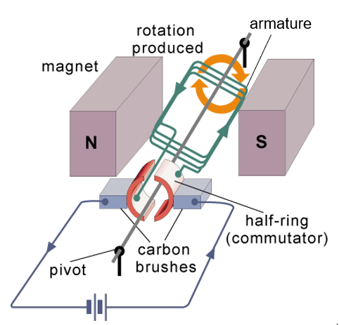
THEORY: DC motors are devices that convert electrical energy into mechanical energy. From the diagram below, it shows the construction of a DC motor. When direct current is supplied in the armature, movement is produced due to electrolmagnetism.
EQUIPMENT:
- DC motor
- Breadboard
- PICkit2
- USB to mini USB cable
- dsPIC30F4011 microcontroller
- SN754410NE quad half H-bridge IC
- 6-pin Header
- 220μF capacitor
- TCRT5000 sensor
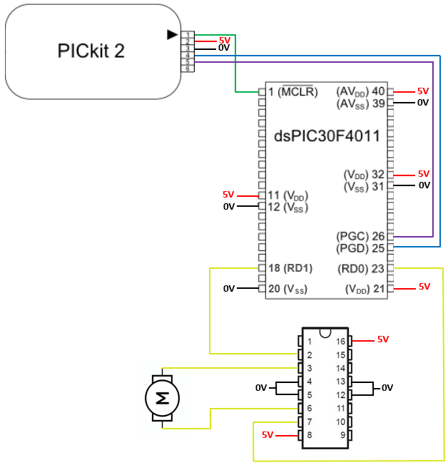
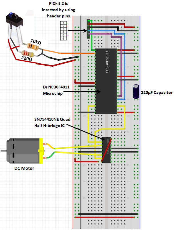
PROCEDURE: RD0 & RD1 were used as the outputs for the motor on the dsPIC30F4011 microcontroller. The driver SN754410NE was then used to provide the motor with the necessary current for it to run, all of the Vss pins were connected to ground while the Vdd pins were connected to the 5V rail powered by the PICkit 2. After the connections in the wiring diagram above were completed, a code in C++ was built to make the DC motor run. The code itself is pretty self explanatory, RD0 & RD1 were made digital outputs and was coded to make the motor, with the motor running forward for 1 second (30000000) then backwards for 1 second.
In order to get the DC motor running, the class was given a dsPIC microcontroller and by looking at the code, the wiring diagram below was built as shown:
RESULTS: From constructing the wiring diagram to run the DC motor, I ended up with the circuit shown below:
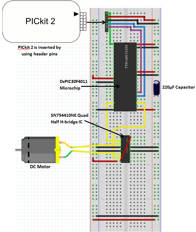
After this circuit was constructed and the code was uploaded to the microchip and the circuit was supplied with 5V from the PICkit. We can see that the code and circuit was successful and I was able to get a video of my DC motor running.
PROCEDURE: I then used another code to make the motor go forwards and reverse. I added in a TCRT5000 sensor and made the DC motor go forward when it sees white (>500) and go backwards when it sees black (<500).


From this code, I then made the necessary connections to get it to work which can be seen from the wiring diagram below, with the sensor coming from analog channel 0 (Pin 2).
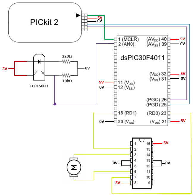
RESULTS: I then ended up with the circuit below when I added the sensor. Note that this sensor is used to detect reflected beams from a surface. The IR LED of the sensor is connected to 5V to the IR unit and through a 220Ω resistor to earth. This allows the IR LED to light up when voltage is applied. The IR unit acts like an open switch when there is no IR light present as it won’t conduct, meaning that the 5V will not pass through the sensor at all. When there is IR light present (i.e. white surface), the 10kΩ resistor decreases the 5V to ground, enabling the microcontroller to sense a logical 1 on the pin. The reason as to why I used the 10kΩ was to dissipate the voltage and to allow the sensor to be grounded.
With the sensor implemented on the circuit, you can see that it goes forward on white and backwards on black.

Overall, excellent. There’s one small problem with the Fritzing diagram for your TCRT5000 circuit. AN0 is connected to ground rather than the node between the phototransistor and the 10k resistor. Apart from that, great diagrams and neat presentation.
Ted
LikeLike