


Arduino with CAN bus Serial Communication
 AUTHOR NAME: Jerico M. STUDENT NUMBER: C15580367 COURSE: DT021A/TU821
Why use CAN bus?
asgsagdsagdsagadsgdsagsadgdsagasgsadgdsagsadgasadgasgdsagsadgadsgasgasFirstly it is important to acknowledge what CAN bus is about. CAN stands for Controller Area Network and is mainly used in vehicles for communication between installed sensors, actuators and electronic control units such as microcontrollers [1]. The purpose of studying this protocol is because it is the main communication system that will be used for the Electric Vehicle (EV) for this project,its purpose allows us to monitor all variables affecting the EV, to ensure that the car is operating under safe conditions and to ensure the safety of the driver and engineers handling the EV. In this case, the CAN bus will have an ECU obtaining multiple variables from sensors around the EV measuring:
- Temperatures
- Currents
- Voltages
- RPM
How does CAN work?
asgsagdsagdsagadsgdsagsadgdsagasgsadgdsagsadgasadgasgdsagsadgadsgasgasTo have an understanding of how CAN works, the standard CAN message frame will be discussed. The image below in Figure 1 shows the standard CAN message from which only consists of an 11-bit ID [2]. An important thing to note is that CAN uses two logic states called dominant and recessive, where dominant state is obtained from a logic 0 on the bus and recessive state is obtained from a logic 1.

Figure 1: Standard CAN Message Frame [2]
- Start of Frame (SOF) is the first bit which is a dominant bit implicating the start of a CAN message.
- The SOF is followed by the 11-bit ID, where priority works from highest priority at smaller ID bits to lowest priority at higher ID bits.
- After this is the Remote Transmission Request (RTR) that is generally a dominant bit which becomes recessive when data is requested from one node to another.
- The Identifier Extension (IDE) is also a dominant bit in a standard CAN message.
- The r0 is a reserved bit which usually is not used but is accepted regardless if it is recessive or dominant.
- This is followed by the Data Length Code (DLC) which is the data itself along with the number of bytes of data.
- There is a Cyclic Redundancy Check (CRC) afterwards, used for error detection in the data being sent, if there are no errors and the message is received, the recessive Acknowledge (ACK) bit is replaced with a dominant bit by the receiver.
- The ACK has a delimiter that synchronizes everything and the transmitter will always try to resend the message if no ACK bit is detected on the bus.
- The End of Frame (EOF) simply represents that it is at the end of the CAN messages.
Note that CAN bus uses a differential transmission system where the differential between two voltage levels called CAN High (CANH) and Can Low (CANL) is obtained, when CANH is dominant or logic 0 CANL is recessive or logic 1 and vise versa, therefore the differential voltage will always be large [1][2].
Arduino with CAN bus Requirements
asgsagdsagdsagadsgdsagsadgdsagasgsadgdsagsadgasadgasgdsagsadgadsgasgasTo implement CAN bus with Arduino the following things are required:
- MCP2515 module for CAN bus communication
- Arduino microcontroller i.e. NANO
- Arduino software
- SPI.h library for communication with the Arduino and MCP2515 module
- MCP_CAN.h library for the MCP2515 module [3]
Before implementing CAN communication with the Arduino, research must be done on each component, technique and library used:
MCP2515 Module and MCP_CAN.h Library
The MCP2515 module is specifically designed for CAN bus communication and utilizes Serial Peripheral Interface (SPI) communication to the Arduino with a pin layout shown below in Figure 2.

Figure 2: MCP2515 CAN bus Module Labelled Pin Layout [4]
The MCP2515 module works well with Arduino as the SPI pins SCK, SI, SO and CS can be used to communication between the module and the Arduino, in addition it also has a 5V DC pin complimenting the 5V from the Arduino, it also has a built-in 120Ω termination resistor that can be used at both ends of the bus along with the CANH and CANL pins to allow for CAN bus. The MCP_CAN.h library can simply be obtained online [3] which is a library for the Arduino software that’s specifically used for the MCP2515 module.
Serial Peripheral Interface (SPI)
Like CAN, SPI is simply a serial communication protocol used for communication between devices such as sensors and microcontrollers. It allows for synchronous communication and has a master and slave topology and also allows for full-duplex communication so the master and slave can communicate data simultaneously [6]. SPI consists of four main pins which has already been specified for the MCP2515 module, these pins can be seen below in Figure 3:

Figure 3: STandard SPI Master and Slave Communication [6]
SCLK – Clock signal provided by the Master to ensure that data is transmission is synchronized.
MOSI – Stands for Master Out Slave In which is the line used to transmit data from the Master to the Slave.
MISO – Stands for Master In Slave Out which is the line used to transmit date from the Slave to the Master.
CS – Stands for Chip Select which is simply the line used by the Master to select which Slave device to transmit data to.
Arduino NANO
For this test the Arduino NANO will be used, the Arduino NANO was chosen since it has all the specifications needed for CAN bus communication, with a pin layout shown below in Figure 4:

Figure 4: Arduino NANO Labelled Pin Layout [5]
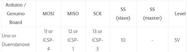
Figure 5: Arduino NANO SPI Pin Layout [7]
Arduino with CAN bus Implementation
asgsagdsagdsagadsgdsagsadgdsagasgsadgdsagsadgasadgasgdsagsadgadsgasgasWith all the required components and research completed, we can begin to implement CAN bus between multiple Arduinos by following the steps below:
- Download the Arduino software and the MCP_CAN.h library (Note that the SPI.h library is already included when the Arduino software is installed).
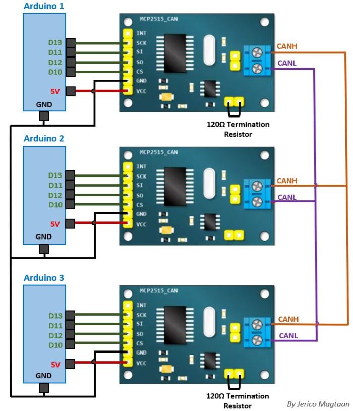
- Set up the circuit below including the SPI connections between each Arduino and MCP2515 modules, along with a common ground, 5V supply from the Arduino and a common CAN bus connection below in Figure 6.
- Create and implement a CAN transmitter and receiver code for each Arduino, as an example, Arduino 1 and Arduino 2 are coded to transmit (code at the end of blog) while Arduino 3 is coded to receive (code at the end of blog).
- With the circuit built and coding implemented, Arduino 3 should start receiving data from both Arduino 1 and Arduino 2 from the bus.
- Open up the “Serial Monitor” on the Arduino software, select the right baud rate and observe that message sent from Arduino 1 and Arduino 2 are being received by Arduino 3.
Three Arduino NANOs are connected to the MCP2515 via SPI pins and 5V supply while all parts are connected to a common ground, whereas all MCP2515 CANH pins are connected on one line and all CANL pins are connected on another line, with the 120Ω termination resistor implemented on both ends of the bus as shown in Figure 6.
Receiver Code:
/********************************************************************
// Receiver Code for CAN bus
// Version 1.0
// Programme by Jerico M.
// Last Edited on 16/02/22
********************************************************************/
/*
* Arduino connected to MCP2515 module via SPI and 5V supply pin:
– Pin D10 of Arduino to CS of MCP2515 module
– Pin D11 of Arduino to SI of MCP2515 module
– Pin D12 of Arduino to SO of MCP2515 module
– Pin D13 of Arduino to SCK of MCP2515 module
– Pin 5V of Arduino to VCC of MCP2515 module
– All Arduino and MCP2515 modules connected to a common ground
– 120 Ohm termination resistor at both ends of CAN bus
********************************************************************//* Import the needed libraries */
#include <SPI.h>
#include <mcp_can.h>MCP_CAN CAN(10); // NANO Chip Select(CS) pin D10
unsigned char len = 0;
unsigned char buf[8];
unsigned int canID;
/* void setup allows to run once */
void setup()
{
/* Start serial port to display results on screen */
Serial.begin(9600);/* Initialize CAN bus at 100KBPS and print if OK or failed*/
START_INIT:if(CAN_OK == CAN.begin(CAN_100KBPS))
{
Serial.println(“CAN BUS Shield init ok!”);
}
else
{
Serial.println(“CAN BUS Shield init fail”);
Serial.println(“Init CAN BUS Shield again”);
delay(100);
goto START_INIT;
}
}
/* End setup */
/* void loop allows to run continuously */
void loop()
{
/* Check for incoming data and print to screen if data is received*/
if(CAN_MSGAVAIL == CAN.checkReceive()) // Check if data is coming
{
CAN.readMsgBuf(&len, buf); // Read data, len: data length, buf: data buffer
canID = CAN.getCanId(); // Get the ID of incoming messageSerial.print(“ID is: “);
Serial.print(canID, HEX); // Print the ID in its standard form (HEX)Serial.print(” Length is: “);
Serial.println(len);for(int i = 0; i<len; i++) // Loop for incoming data to print on screen
{
Serial.write(buf[i]); // Print characters received
}
Serial.println(“\n\t*********************************************\n”);
}
}
/* End main loop */
/*******************************************************************/
Transmitter Code:
/********************************************************************
// Transmitter Code for CAN bus
// Version 1.0
// Programme by Jerico Magtaan
// Last Edited on 16/02/20
********************************************************************/
/*
* Arduino connected to MCP2515 module via SPI and 5V supply pin:
– Pin D10 of Arduino to CS of MCP2515 module
– Pin D11 of Arduino to SI of MCP2515 module
– Pin D12 of Arduino to SO of MCP2515 module
– Pin D13 of Arduino to SCK of MCP2515 module
– Pin 5V of Arduino to VCC of MCP2515 module
– All Arduino and MCP2515 modules connected to a common ground
– 120 Ohm termination resistor at both ends of CAN bus
********************************************************************//* Import the needed libraries */
#include <SPI.h>
#include <mcp_can.h>MCP_CAN CAN(10); // NANO Chip Select(CS) pin D10
/* void setup allows to run once */
void setup()
{
/* Start serial port to display results on screen */
Serial.begin(9600);/* Initialize CAN bus at 100KBPS and print if OK or failed*/
START_INIT:if(CAN_OK == CAN.begin(CAN_100KBPS))
{
Serial.println(“CAN BUS Shield init ok!”);
}
else
{
Serial.println(“CAN BUS Shield init fail”);
Serial.println(“Init CAN BUS Shield again”);
delay(100);
goto START_INIT;
}
}
/* End setup */
/* 8 bytes of CAN message spelling “Cartera!” loaded */
unsigned char data[8] = {‘C’, ‘a’, ‘r’, ‘t’, ‘e’, ‘r’, ‘a’, ‘!’};
/* void loop allows to run continuously */
void loop()
{
/* Send bytes of data to bus and print on monitor */
Serial.println(“entered communication loop”);
CAN.sendMsgBuf(0xF1, 0, 8, data);
delay(2000);
}
/* End main loop */
/*******************************************************************/
References
[1] https://www.csselectronics.com/screen/page/simple-intro-to-can-bus/language/en
[2] https://www.allaboutcircuits.com/technical-articles/introduction-to-can-controller-area-network/
[3] https://github.com/Seeed-Studio/CAN_BUS_Shield
[5] https://www.arduino.cc/en/uploads/Main/ArduinoNanoManual23.pdf
[6] https://www.analog.com/en/analog-dialogue/articles/introduction-to-spi-interface.html#
