


Colour-Sorting Conveyor
STUDENT NAME: Jerico M. STUDENT NUMBER: C15580367
Abstract
My idea for this mini-project was to build a colour-sorting conveyor. The idea is pretty simple where I’ll have a DC motor running the conveyor belt, a sensor at the beginning of the conveyor belt to detect the colour of the placed objects and a servo motor altering the path the objects go to depending on the colour of the object. Although the initial idea was to use multiple servo motors to separate more colours, because of time constraints and limited access to materials, I was only able to build a smaller scale project which would only separate black objects.
I feel like this project is relevant because it represents a lot of the machinery and systems that’s already used in all or most factories. Colour-sorting conveyors are especially important when it comes to mass produced goods, for example for toy factories such as lego, they would need huge conveyor belts to distinguish the colours of each piece and separate them. This is just one example but you can see just how vital this mechanism is, the best part about it is just by changing the sensors, this concept can cover even more areas, i.e. sensors can be changed to separate the objects based on size, they can also be changed to separate objects based on mass, etc… The list goes on.
The most complicated issue that I encountered in this project was the positioning of the servo motor and timing both the DC and servo motors. Since I decided to build the conveyor first, it made it hard for me to code the servo motor because I had to identify the exact angle the servo motor needed to turn for the objects to change its path smoothly without causing disturbances to the conveyor belt because if the barrier is to low, it would end up scraping against the running conveyor. I also had to estimate the duration of time the barrier had to go down for since my conveyor didn’t run smoothly due to the way it was built. For both of these issues, I just had to play around with the numbers until I found the optimum result.
Introduction
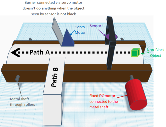
As discussed already, the plan was to build a small scale project to imitate the fundamentals of a colour sorting conveyor. The first thing I did was draw a rough design for my project which can be seen in the image below.

As you can see, the design is pretty straight forward, I would need wood as a base to hold the whole conveyor together, two rollers in both ends of the conveyor belt to make it spin, metal shafts going through the wood and the roller to hold it in place and also to allow the DC motor to be connected to the shaft and make the conveyor run. I would then need the servo motor fixed at an angle to allow the barrier to make objects change paths smoothly and the sensor to be held in place somewhere along the start of the conveyor belt.
When a non-black object is placed at the start of the conveyor, the conveyor starts to move until it reaches the sensor, the conveyor stops for 2 second at this point to show that the sensor is able to check the colour of the object. Since the object is a non-black object, it would go straight and take path A.
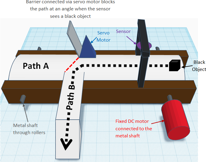
But when a black object is placed, when it reaches the sensor, the conveyor stops for 2 second and the servo turns making the attached barrier block the path. The conveyor then runs again except this time the object takes path B since the barrier is blocking path A due to the sensor seeing black.
Building the Conveyor
EQUIPMENT:
- Abascus pieces
- Small bolts
- Thin metal shafts
- Electrical tape
- Any stretchy fabric/material for the conveyor belt
- Wooden popsicle sticks
- Small tin boxes
- DC motor
- Servo motor
- Super glue
- Drill
- Hand saw
PROCEDURE:
The first thing I did was make the roller, one of my classmates gave me abascus pieces that can be easily found in children’s toys as shown below. They were perfect because of their round and cylindrical shape which would allow the conveyor to spin smoothly.
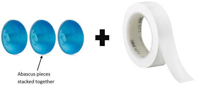
I simply stacked each abascus piece on top of each other until they added up to the width of the material I was using for my conveyor belt. I glued each piece together then wrapped it with electrical tape so there’s more friction between the roller and the conveyor belt. The result can be seen below.

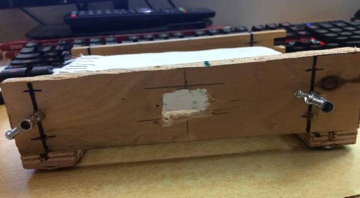
Since I’ve already found a stretchy fabric to be used for my conveyor belt, I simply stapled the ends together and sawed four pieces wood to the length of my conveyor belt and rollers to start making the base of my conveyor. I had two thin blocks of wood which had the same length as my conveyor belt and another two small planks of wood which was roughly the same length as my rollers. I then drilled holes in the planks of wood and connected them together with screws and nails to make the frame for my conveyor.

With the frame built, I was able to choose the position for my rollers. I drilled through the center of my rollers and through the wood to fit my thin metal shaft, in order to provide a secure connection between my conveyor belt and the frame. I placed my rollers and conveyor belt and held the shaft in place by screwing bolts in each end.
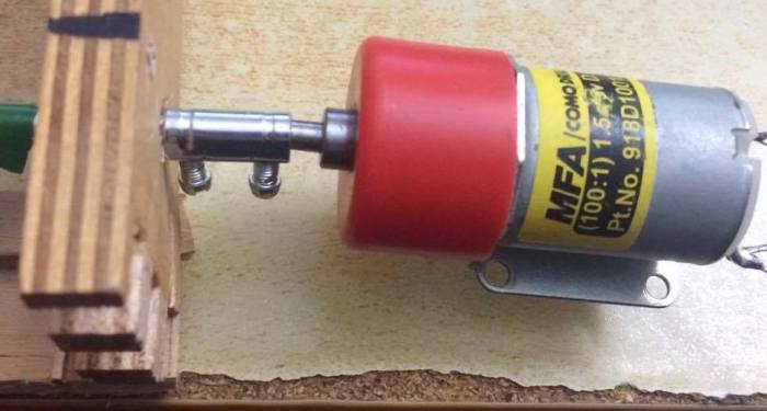
With the big stuff done, I was finally able to implement the motors and the sensor. The DC motor was simply attached to the shaft and held in place by screwing a bolt into it as shown below.
I then cut a wooden popsicle stick to match the width of the conveyor belt and taped it to the servo motor to act as a barrier.
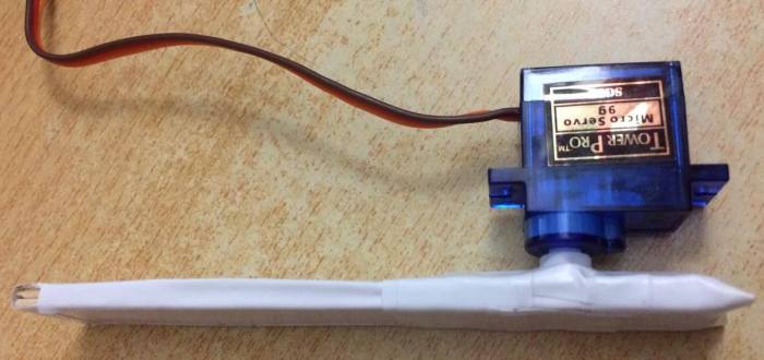
I made sure that the servo motor was glued in place at an angle to ensure that the objects move along the barrier smoothly into the chute.
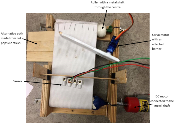
Lastly, I glued and taped together more wooden popsicle sticks to implement an elevated chute to make sure that the objects slide down the alternative path consistently without getting stuck. Now that all of these steps have been carried out, I was finished with the final design for my conveyor, which can be seen below.
Circuit Build and Coding for the Conveyor
EQUIPMENT:
- DC motor
- Servo motor
- TCRT-5000 sensor
- Breadboard
- PICkit2
- USB to mini USB cable
- dsPIC30F4011 microcontroller
- SN754410NE quad half H-bridge IC
- 6-pin Header
- Power supply
- 220μF capacitor
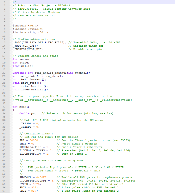
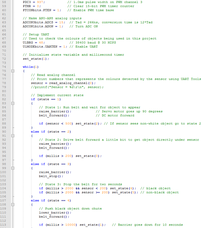
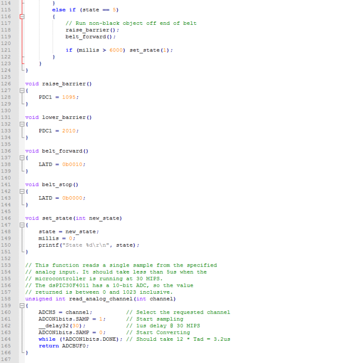
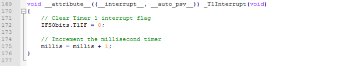
PROCEDURE: The first step that I carried out was to write the code for my conveyor. What I wanted was, when the sensor at the start of the conveyor sees a non-white object, the conveyor will stop for 2 seconds, the barrier will then block the path depending on its colour. If the object isn’t black, the barrier is raised up but if the object is black, the barrier goes down which separates all of the black objects. To implement this, I wrote the code shown below:
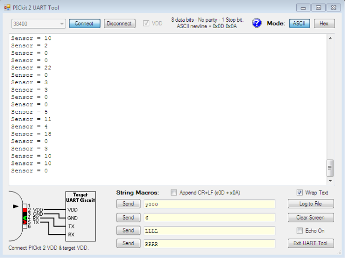
I then used the UART tool on the PICkit 2 Programmer to find out the exact colour of my object so I know what number to implement in my code. When I hovered my sensor on my black object it showed the values below, numbers were very low so I decided to use <200 for black in my code just to be safe.
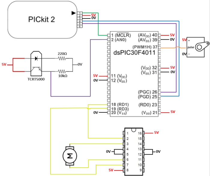
From the code, I then made a wiring diagram to show the appropriate connections required for my motors and sensor to function:
Results
I ended up with the circuit below by following the wiring diagram. From the circuit diagram, you can see that I used 5V from the PICkit 2 to power the sensor and the DC motor using the left hand side rail and I used a 5V power supply on the right hand side rail to power the servo motor.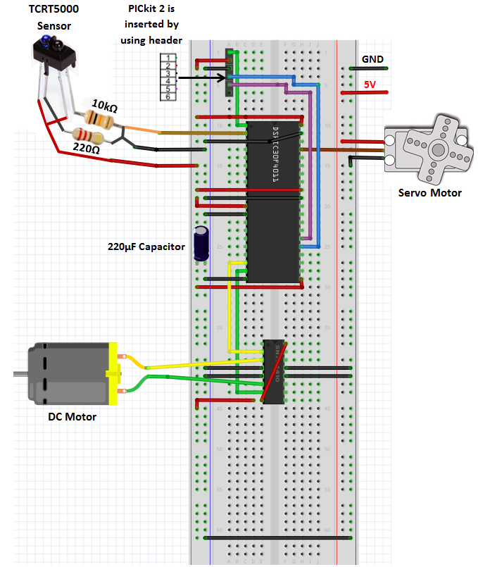
With the circuit and conveyor built and the code implemented, I was able to get a video of my conveyor running just how I wanted it to.

This is super stuff! Excellent demo and very nicely presented here.
Ted
LikeLike