


Electric Car Tractive System
 AUTHOR NAME: Jerico M. STUDENT NUMBER: C15580367 COURSE: DT021A/TU821
Week 8, 9 & 10 Objectives
basgsagdsagdsagadsgdsagsadgdsagasgsadgdsagsadgasadgasgdsagsadgadsgasgaDue to the social distancing measures required for COVID19, all campuses have been closed until the 29th of March, thus the objectives for these coming weeks have to be heavily altered, due to lack of equipment since there is no access to vital components needed for this project, thus the following objectives for this week and the following weeks have been set out below:
- Data logging sensor measurements on an SD card via the Arduino
- Implement watchdog timer with Arduino: To prevent infinite loops in system
- Implement an efficient method for a signal-check code between two Arduinos that can be used for the LVCSS Arduino to constantly check if Lowry’s Arduino is still running:
- Inter-Integrated Circuit (I2C) Signal Check
- Serial Peripheral Interface (SPI) Signal Check
- Digital Pin Signal Check
- Implement CAN bus for the following sensors:
- BMS Temperature Sensors
- Speed Sensors (Lowry’s code)
- Motor/Drive Current
- Motor/Drive Voltage
- Motor/Drive Power
EV Tractive System & LVCSS Progress
asgsagdsagdsagadsgdsagsadgdsagasgsadgdsagsadgasadgasgdsagsadgadsgasgas
SD Card Data Logging
In the group meeting on Wednesday 25/03/20 I proposed the idea of having some sort of data logging system on the Arduino. The idea behind this is, since my Arduino is measuring variables from multiple parts of the EV i.e. BMS temperature, motor voltage, current and power, etc… It would be a good idea to be able to apply a data logging system for these variables so that when the car is running, these measurements would be logged and further study of the component parts such as the BMS and motor behaviour under driving conditions can be checked. Since I already have the components to carry this out, my supervisors have agreed that it is a great addition to the project.
This section will be updated in a separate blog upon successful implementation in Week 10 (Starting 30/03/20).
Note: (Digital signal check will also be covered in the next blog).
Arduino Watchdog Timer (WDT)
The purpose of implementing a watchdog timer is to prevent infinite loops in the chosen microcontrollers that will be installed on the EV. Since Arduino already comes with a prebuilt watchdog timer, this feature might aswell be utilized to minimize errors within the EV systems. The Arduino’s internal WDT basically works as a separate device that allows for an output reset after it has not received a periodic pulse signal from the Arduino within a chosen time frame specified in the program , for example the Figure 2 is a perfect example of the Arduino WDT configuration on the microcontroller. With this in mind, the process of WDT can be described as follows:
State 0: The program runs as normal and WDT detects no fault.
State 1: A fault occurs within the WDT and is able to detect the fault.
State 2: A fault occurs within the WDT and is unable to detect the fault.
State 3: The Arduino runs with a specific program calling the WDT.
State 4: Errors within the Arduino occur and is detected by the WDT, causes the WDT to reset.
State 5: Errors within the Arduino occur but remains undetected by the WDT, no reset meaning the Arduino goes into an infinite loop or microcontroller damage.

Since the Arduino Uno will be used for this project, the datasheet of the ATMega328P chip was studied. Since the Arduino Uno already has the WDT built-in, the library can simply be called using “#include <avr/wdt.h>” in the program. The WDT in the ATMega328P has a register consists of one byte, which has eight bits that can be configured as ON or logic “1” and OFF or logic “0”, these bits are:
WDT Register Bit Bit Name
7 WDIF
6 WDIE
5 WDP3
4 WDCE
3 WDE
2 WDP2
1 WDP1
0 WDP0
WDIF: This bit is used to set an interrupt flag, the Arduino automatically flags this bit.
WDIE: This bit enables interrupts for the WDT of the Arduino.
WDCE: This bit can simply be used as a configuration mode as calling this bit, will allow a configuration mode that would last for four clock cycles.
WDE: This bit is used to enable the system reset based on the chosen WDT timeout.
WDP3/WDP2/WDP1/WDP0: A combination of these pins determines how long the timer should time before resetting the Arduino, allows for a time between 16ms to 8s, this part is easily carried out by including the WDE bit in the program with the function: “wdt_enable(WDTO_2S)”, this function simultaneously sets the WDT timeout and enables the WDT.
With this background theory studied, the WDT in the Arduino can be implemented using Arduino WDT functions. The code below can easily be applied or added to any existing Arduino program as it wouldn’t affect the functionalities of the code, although an important thing to note is to include the “wdt_reset()” within the main loop of the program, the way it should work is that the Arduino should always be able to reset the WDT counter within the loop, if it fails to reset this within the loop within the specified WDT timeframe, it basically means that the loop was not able to reach this point, thus the WDT resets the Arduino. In addition, from looking at many examples and the library, it is important to include a 2 to 3 second delay before enabling the WDT to allow the Arduino’s bootloader to check for a new code being uploaded to the microcontroller.
With this information, the code below was completed and the Arduino successfully reset via the WDT by implementing a dummy infinite while loop “while(1);”, this can be seen through the serial monitor in Figure 3 and Figure 4, where a set of serial.print functions were used to troubleshoot the microcontroller, without the infinite loop, the program ran as normal but with the infinite loop, the microcontroller resets as configured.
/********************************************************************
– Watchdog Timer for Arduino with Simple Reset
– Version 1.0
– Modified by Jerico M.
– Last Edited on 25/03/22
********************************************************************/
/*
This code can be used on any Arduino, its function is to simply
show how watchdog timer can be configured where it allows for
different watchdog timer timeout between 15ms to 8s:
WDTO_15MS 15
WDTO_30MS 30
WDTO_60MS 60
WDTO_120MS 120
WDTO_250MS 250
WDTO_500MS 500
WDTO_1S 1000
WDTO_2S 2000
WDTO_4S 4000
WDTO_8S 8000
********************************************************************/
/******* Import the needed libraries for the sensor to work ********/
#include <avr/wdt.h> // Header for watchdog timers in AVR
/* void setup allows to run once */
void setup()
{
/* Start serial port to display results on screen */
Serial.begin(9600);
Serial.println(“——————————————“);
Serial.println(“Watchdog Timer Example Setup Initializing”);
pinMode(13, OUTPUT);
wdt_disable(); // Disable the watchdog
delay(2000); // Done to let bootloader check for new code to prevent infinite loop
wdt_enable(WDTO_2S); // Enable the watchdog with a timeout of 2 seconds
Serial.println(“Watchdog Timer Enabled (With 2s timeout)”);
}
/* End setup */
/* void loop allows to run continuously */
void loop()
{
Serial.println(“>>Entering Main Loop<<“);
/* This part is a dummy code, this is where Lowry’s main code will go */
for(int i = 0; i<20; i++) // Blink LED for some time
{
digitalWrite(13, HIGH);
delay(100);
digitalWrite(13, LOW);
delay(100);
wdt_reset(); // Reset the watchdog
}
Serial.println(“>>Main Loop Finished<<“);/* Infinite loop placed in the end to show watchdog timeout and reset */
while(1); // Can comment this loop out to show that the Arduino continues
// to work without resetting, but with the infinite loop,
// after 2s, watchdog timer detects this and resets the Arduino
} /* End main loop */
/*******************************************************************/

Figure 3: Arduino Results Without Infinite Loop

Figure 4: Arduino Results With Infinite Loop (System Reset)
Arduino LVCSS Signal Check
Another important task for this project is to have a safety measure in the case where Lowry’s Arduino dies, since his Arduino tracks and controls the brake position and steering position of the EV, it would need to be stopped, thus the signal check comes into play. If the LVCSS Arduino detects that Lowry’s Arduino has stopped sending constant signals completely after a given timeframe, the LVCSS Arduino can trip the relay in the LVCSS and shut the system down, thus multiple methods are going to be studied, to see the most efficient way in terms of, application, ease of implementation and reliability of the method.
I2C Communication Signal Check
The first method studied is the Inter-Integrated Circuit or I2C serial communication protocol, or referring to the Uno ATMega328P chip datasheet, Two-Wire Serial Interface. It is a synchronous serial communication method, meaning that devices using this protocol requires a common clock signal. This method only requires two wires, one used for the clock signal and the other used for bi-directional data transmission between multiple devices where:
SCL (Serial Clock): Is the line that shares the common clock signal between devices.
SDA (Serial Data): Is the line used for transmitting and receiving data between devices.
This protocol uses the master and slave configuration, where it allows for multiple masters and multiple slaves on the same bus as specified below in Figure 5:
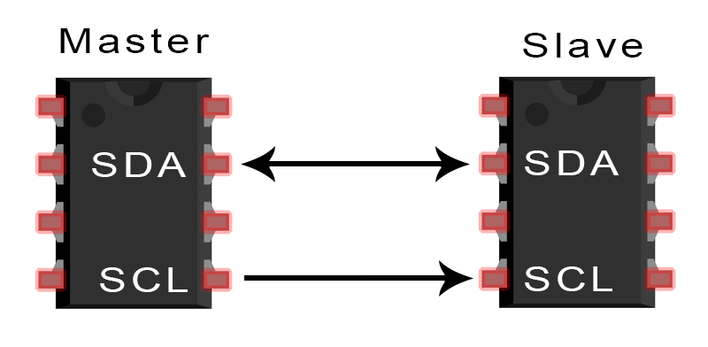
The reason this protocol was chosen was compared to other commonly used protocols such as Serial Peripheral Interface (SPI) is because of its ease of use with the Arduino Uno. The Arduino already has the required libraries and built-in pins for I2C, furthermore it also uses fewer connections compared to SPI. Since the purpose of this is to only have a signal-check, I2C would be sufficient for this task. Before applying this protocol on the Arduino, its functionalities must be studied, see Figure 6.
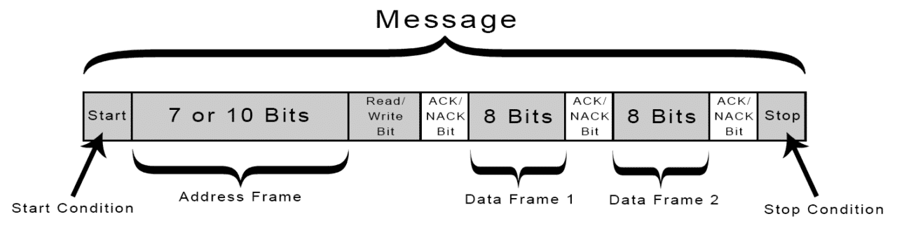
Figure 6: Standard I2C Message Structure
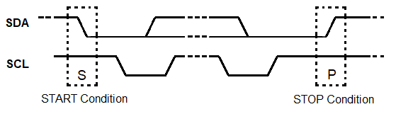
Start & Stop Condition: A message starts with the master initiating a Start Condition, where a high to low transition on the SDA line occurs, before a high to low transition on the SCL line (SCL High defines the Start Condition), at the end of a message, the opposite happens for the Stop condition where there is a low to high transition on the SDA line, after a low to high transition on the SCL line, as shown below in Figure 7:
Address Frame: After the Start Condition, it is followed by the 7 or 10 bit address frame, this is the unique address given to slave devices connected on the I2C bus.
Read or Write Bit: This is then followed by a single read (high “1”) or write (low “0”) bit from the master to the slave device.
ACK or NACK Bit: After a byte of data (8 bits) is sent, it is followed by a 9th bit which is the bit for ACK or NACK. If the address frame and/or data frame was successfully transmitted, the receiver sends an ACK bit to the transmitter to let it know it has received the data, at this point, the receiver pulls down the SDA line to send an ACK before the 9th clock pulse, but if it doesn’t pull the SDA line low before the 9th clock pulse,it is considered a NACK as the receiver has failed to receive data.
Data Frame: This is located after the address frame has been successfully sent, thus data can start being transmitted. This consists of a 8 bits, where the master generates a constant clock pulse between all connected devices while data is transmitted on the SDA line.
With this theory acknowledged, it can be applied and tested between two Arduinos. A configuration of having Lowry’s Arduino (Master Arduino) constantly sends a message to the receiving LVCSS Arduino (Slave Arduino). After multiple tests of I2C between two Arduinos, I was able to identify that the receiving LVCSS Arduino holds on to the last transmitted message, thus I was able to use a time condition to show that if the same transmitted message has been received over a given timeframe, either the I2C lines have been disconnected or the Master Arduino is no longer running. Results can be seen in Figure 8.
Lowry’s Arduino – Master Code:
The Arduino comes in with a pre-installed library for I2C which can be called using “#include <Wire.h>”. In this example variable x is sent from the Master Arduino to the Slave Arduino every 500ms. Using the library, the library to start I2C communication can simply be started using “Wire.begin();” in the setup. Referring to the I2C message structure before, the start condition for I2C must be specified at a chosen slave address, this can be called using the function “Wire.beginTransmission(5);” where a Start Condition to send data to the slave address of 5 is initiated. The data stored in the integer x is then sent over the SDA line using “Wire.write(x);”, after this variable has been transmitted, the stop condition is applied with the function “Wire.endTransmission();”.
/********************************************************************
– Arduino to Arduino I2C Serial Communication Test (I2C Master Code)
– Version 1.1
– Modified by Jerico Magtaan
– Last Edited on 25/03/20
********************************************************************/
/*
* The purpose of this code is to investigate if I2C can be used as a
* handshake protocol for the LVCSS to Lowry’s Arduino (speed sensors, etc)
* Two Arduinos are connected to each other using built-in I2C pins:
– Pin A4 (SDA) of Master Arduino to Pin A4 (SDA) of Slave Arduino
– Pin A5 (SCL) of Master Arduino to Pin A5 (SCL) of Slave Arduino
– GND pin of both Arduinos connected to a common ground
********************************************************************/
/******* Import the needed libraries for the sensor to work ********/
#include <Wire.h>/************** Declare variables that will be used ***************/
int x = 0;
/* void setup allows to run once */
void setup()
{
/* Start serial port to display results on screen */
Serial.begin(9600);
Serial.println(“| I2C Master Initiated |”);/* Start up the I2C bus */
Wire.begin();
Serial.println(“——————————————-“);
}
/* End setup */
/* void loop allows to run continuously */
void loop()
{
/* Use the I2C bus to send data from the Master to the Slave */
Wire.beginTransmission(5); // Transmit to device with address 5
Wire.write(x); // Send variable x
Wire.endTransmission(); // Stop transmission
Serial.println(“>>Variable Transmitted to Address 5<<“);/* Variable x constantly sent to Slave Arduino to let it know it’s alive */
x++; // Variable x incremented by 1 each time
delay (500); // 0.5 second delay
if (x > 1) // If variable x greater than 1, make x = 0
{
x = 0;
}
}
/* End main loop */
/*******************************************************************/
LVCSS Arduino – Slave Code:
The LVCSS Arduino is programmed to simply receive the data from the variable x from the SDA line. Again the library “#include <Wire.h>” must be called, in the setup the LVCSS Arduino can be configured with the slave address of “5” using the function “Wire.begin(5);” and to start receiving data using “Wire.onReceive(receiveEvent);” where in this event, the bits of data in variable x is read using “x = Wire.read();”. Since the Master Arduino was programmed to send values of 0 and 1 to the Slave Arduino every 500ms, a simple time condition of for example 4s was applied. Since I discovered that the Arduino holds the last value of x that was sent, the time condition was simply set to say that if the value received of 1 or 0 has been received for equal to or more than 4s, print to the serial monitor that the Master Arduino is no longer running, thus the code for the LVCSS comes into play here, where it can be coded to shut off the LVCSS and the running of the EV.
/********************************************************************
– Arduino to Arduino I2C Serial Communication Test (I2C Slave Code)
(This version includes a time condition, Master sends x value of 0 to
1 every 0.5 seconds over the I2C bus, if either 0 or 1 is held for more
than four seconds, that means the Master Arduino is not operating)
– Version 1.1
– Modified by Jerico Magtaan
– Last Edited on 25/03/20
********************************************************************/
/*
* The purpose of this code is to investigate if I2C can be used as a
* handshake protocol for the LVCSS to Lowry’s Arduino (speed sensors, etc)
* Two Arduinos are connected to each other using built-in I2C pins:
– Pin A4 (SDA) of Slave Arduino to Pin A4 (SDA) of Master Arduino
– Pin A5 (SCL) of Slave Arduino to Pin A5 (SCL) of Master Arduino
– GND pin of both Arduinos connected to a common ground
********************************************************************/
/******* Import the needed libraries for the sensor to work ********/
#include <Wire.h>/************** Declare variables that will be used ***************/
int x = 0;
unsigned long x1LastTimeConditionWasFalse;
unsigned long x0LastTimeConditionWasFalse;
/* void setup allows to run once */
void setup()
{
/* Start serial port to display results on screen */
Serial.begin(9600);
Serial.println(“| I2C Slave Initiated |”);/* Start up the I2C bus */
Wire.begin(5); // Slave address of 5
Wire.onReceive(receiveEvent);
Serial.println(“——————————————“);
}
/* End setup */
/* void loop allows to run continuously */
void loop()
{
/* Print received x value from the Master Arduino to serial monitor */
Serial.println(x); // x = received variable
delay(500); // 0.5 second delay/* Condition to count the duration that x not equal to 1 */
if (x != 1)
{
x1LastTimeConditionWasFalse = millis();
}
/* Condition to show that x equal to 1 for more than four seconds
* (When Master Arduino is disconnected, holds last sent value) */
if (millis() – x1LastTimeConditionWasFalse >= 4000)
{
Serial.println(“Master Arduino not operating, turn off system (1)”);
// Code for Low Voltage System to use relay to turn off system here
}
/* Count the duration that x not equal to 0 */
if (x != 0)
{
x0LastTimeConditionWasFalse = millis();
}
/* Condition to show that x equal to 0 for more than four seconds
* (When Master Arduino is disconnected, holds last sent value) */
if (millis() – x0LastTimeConditionWasFalse >= 4000)
{
Serial.println(“Master Arduino not operating, turn off system (0)”);
// Code for Low Voltage System to use relay to turn off system here
}
}
/* End main loop */
/* Function to read values for variable x from I2C bus */
void receiveEvent(int bytes)
{
x = Wire.read();
}
/*******************************************************************/

Figure 8: I2C Results Between Master Arduino and Slave Arduino
CAN bus Address Structure for EV
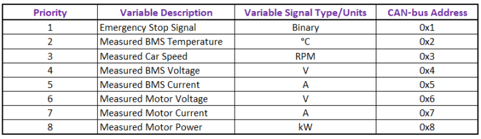
After discussing the CAN address structure with Raimonds, the address structure has been finalized. Looking at the Week 3 blog, the theory with CAN bus shows that the lowest number address is considered the highest priority, therefore we structured and agreed on the addresses based on this. The final addresses can be seen below, taken straight from the Arduino program for the SCADA system:

From this part of the program, it can be seen that the importance of variables in the EV from highest (1) to lowest (8) are:
Week 8, 9 & 10 Objectives Checklist
asgsagdsagdsagadsgdsagsadgdsagasgsadgdsagsadgasadgasgdsagsadgadsgasgasRed = Incomplete Green = Complete
- Data logging sensor measurements on an SD card via the Arduino
- Implement watchdog timer with Arduino: To prevent infinite loops in within the Arduino program, can be applied to any Arduino in the EV
- Implement an efficient method for a signal-check code between two Arduinos that can be used for the LVCSS Arduino to constantly check if Lowry’s Arduino is still running:
- Inter-Integrated Circuit (I2C) Signal Check
- Serial Peripheral Interface (SPI) Signal Check
- Digital pin signal check
- Implement CAN bus for the following sensors:
- BMS Temperature Sensors
- Speed Sensors (Lowry’s code)
- Motor/Drive Current
- Motor/Drive Voltage
- Motor/Drive Power
